The primary focus of the Steam group is the Coos Bay #11 steam locomotive. In January 2018, a 29-page report to the museum’s board of directors was prepared that details the work that has been done, and what work is needed to restore the Coos Bay to operation. In addition, it included a report from restoration consultant, Stathi Pappas, and his estimate of $300,000 to $400,000 in expenses to complete the project. Costs will vary, depending on how much work can be done in-house and how much needs to be contracted out. The museum simply does not have the in-house skills to do the entire job. At their March, 2018, meeting the board agreed that it was a good report, but since they were in the process developing a master plan, no fund-raising for the Coos Bay should take place at this time. In the meantime, work should continue with the take-apart evaluation of the condition of the engine to document what repairs will be needed. So far, it has been determined that the major work that will need to be contracted out is to replace the lower third of the side sheets in the fire box, replace the hub liners on the drivers, and replace the lower third of the smoke box. Also some small cracks and grooving in the fire box area will need to be addressed.
Since September 2016, we have completed the following:
Ground off the seal welds on the tubes on the rear tube sheet and the tube stubs removed.
Travus Clark grinds off seal welds
There were a total of 26 super heater flues and 160 – 2″ tubes. The sheet was then cleaned up, and tested with dye penetrant. A number of small cracks radiating from tube holes were found. It has not yet been determined if these are a significant factor that could require the entire sheet being replaced. If not significant, only the top portion will need to be replaced, due to an existing crack.
Rear tube sheet showing crack at the knuckle
Purchased a used 40-foot cargo container to use for storing parts that have been removed from the Coos Bay, and the other steam engines owned by the museum. A heavy-duty set of shelves was constructed in the container. The engine parts had filled an ex-UP boxcar to overflowing, so those parts were moved to the container so that the tools that are also stored in the box car could be better organized. So far about 310 separate parts have been removed and inventoried. That doesn’t count multiples of the same thing, i.e. 8 brake heads or 26 superheater units.
Removed, cleaned and replaced several hundred flexible stay bolt caps/plugs. Except for 2 or 3 very stubborn ones, this job is done. Completed ones were painted green.
Stay bolt caps on 4-inch centers. Caps painted green have been removed and cleaned.
Radiographed some existing boiler patches and a couple of areas suspected of having “grooving.” As had been suspected, some existing boiler patches and a couple of other areas had cracks or grooving that will need to be addressed.
Removed 7 of 8 pins that support brake hangers. These support the brake shoes for the drivers. One refuses to be removed. We’ve heated, cooled, and lubricated to no avail.
Jim Baker attempting to remove a stubborn brake hanger pin
Needle-gunned all 8 drivers, then followed that by dye penetrant testing of all the spokes for cracks. No cracks were found.
Painted the following areas with gloss black paint: front and rear pilots, the bottom of the boiler, the fuel bunker, the drivers, the sides of the cab and the entire outside of the saddle tank, except its rear end.
Before and after shot of painting the fuel bunker
Jim Baker and Tim Wamsley paint the saddle tank
Did some ultra-sound testing on the saddle tank to determine the thickness of the steel. Some areas seem to be eroded away enough that they might need replacing. More work is needed on this. The saddle tank was filled with about 250 gallons of water on each leg, about 2 feet deep, and let it stand overnight. There were no leaks observed.
Removed the cab/fuel tank (without the deck). The fuel tank forms the rear, and major, part of the cab. There are two reasons for removing the cab: 1) to access the top of the rear part of the boiler, and 2) to access the ceiling of the cab to refinish and/or replace the wooden tongue and groove siding. To prepare for this, the steam pipes that supply the injectors on each side, the rear cab windows, the rear cut lever, the main fuel hose, the grab irons on both sides of the doors, the front, center section of the cab, and the steam heat line from the fuel tank to the cab were removed.
Cab windows removed for cab separation.
To add some rigidity to the cab for when it was lifted, several angle iron braces were added across open areas: the doorways, the front windows and across the upper front of the cab where the center section was removed. Using information from the ALCO blueprints for the locomotive, and data about the weight of steel, the weights involved were calculated. The cab rigged so that the main lifting cables were attached to brackets on the tank that secure it to the locomotive frame. Lifting straps were secured to the cab front window frames and led back to the crane hook to stabilize the load. The cab was lifted off the locomotive and set on a flat car. No problems were encountered.
Cab being removed from the frame by our former ATSF overhead gantry crane.
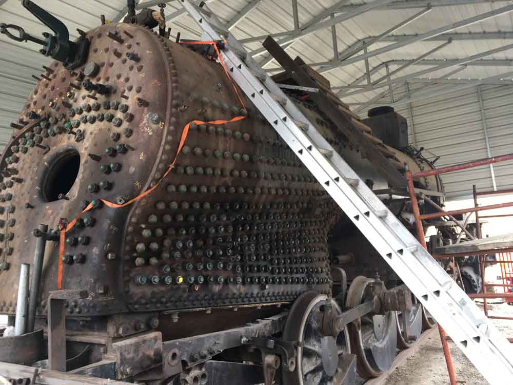
With cab removed, this is all that remains attached to the frame on CBL #11.
Cab and saddle tank rest patiently on one of the Museum's DODX flat cars.
The frame was cleaned and tested with dye penetrant to look for cracks; a crack was found in the “bumper knee” an L-shaped piece that attaches the rear bumper to the left frame. A similar crack was found earlier on the right side.
With the frame now cleaned, but with the cab and its floor being removed, a way was needed to access the upper part of the boiler. A sheet of plywood, reinforced with 2 x 4 studs, was bolted to the frame.
Donovan Chorney and Harry Linebeck pose atop the temporary plywood decking
Other parts removed include:
- All valve stems and pipes from turret.
- Brake stand and associated plumbing.
- Johnson bar and its quadrant; throttle linkage
- Air brake distributing valve from under cab deck
- Engineer’s and fireman’s sides of cab deck
- Angle iron support for front of center section of the cab deck
- Two damper control levers
- Cab ladders, both sides
- Cab deck supports, both sides
- Rear section of fireman’s side running board and its support to access stay bolts. Replaced fireman’s side support for running board after removal and cleaning of stay bolts.
- Fuel line with heater and its supports along with fuel line from heater to burner.
Ron Amberger, a mechanical engineer and retired professor of the subject, has volunteered to do the “Form 4″ calculations for us. Form 4, a Federal Railroad Administration document, ends up calculating the maximum allowed working pressure for a locomotive boiler. The calculations are done using the thickness measurements of the boiler, along with the diameters of various braces. These calculations will yield a value in pounds per square inch. The maximum allowed working pressure of the boiler is 1/4 of that number. While the majority of the thickness measurements were done back in 2014, we recently did some more work in this area:
- We wire brushed and ground smooth spots for ultrasound exam on the steam dome cap and the boiler in area of turret and the rear tube sheet and did UT measurements..
- Measured the front tube sheet braces and 2 center rear tube sheet braces
- Cleaned and measured a broken stay bolt at the left back head
At this point, we have completed most of the disassembly work that we believe is necessary to prepare the locomotive for the required boiler and running gear work. When the Form 4 calculations are completed, we’ll know if the basic structure of the boiler is sound enough to proceed with a restoration.
In the meantime, we will get a coat of paint on the areas we haven’t previously painted and then start cleaning and painting the parts we have removed. This will include evaluating these parts as to if they can be reused or if new ones will be needed for restoration. We will also try hydro-testing the superheater units.
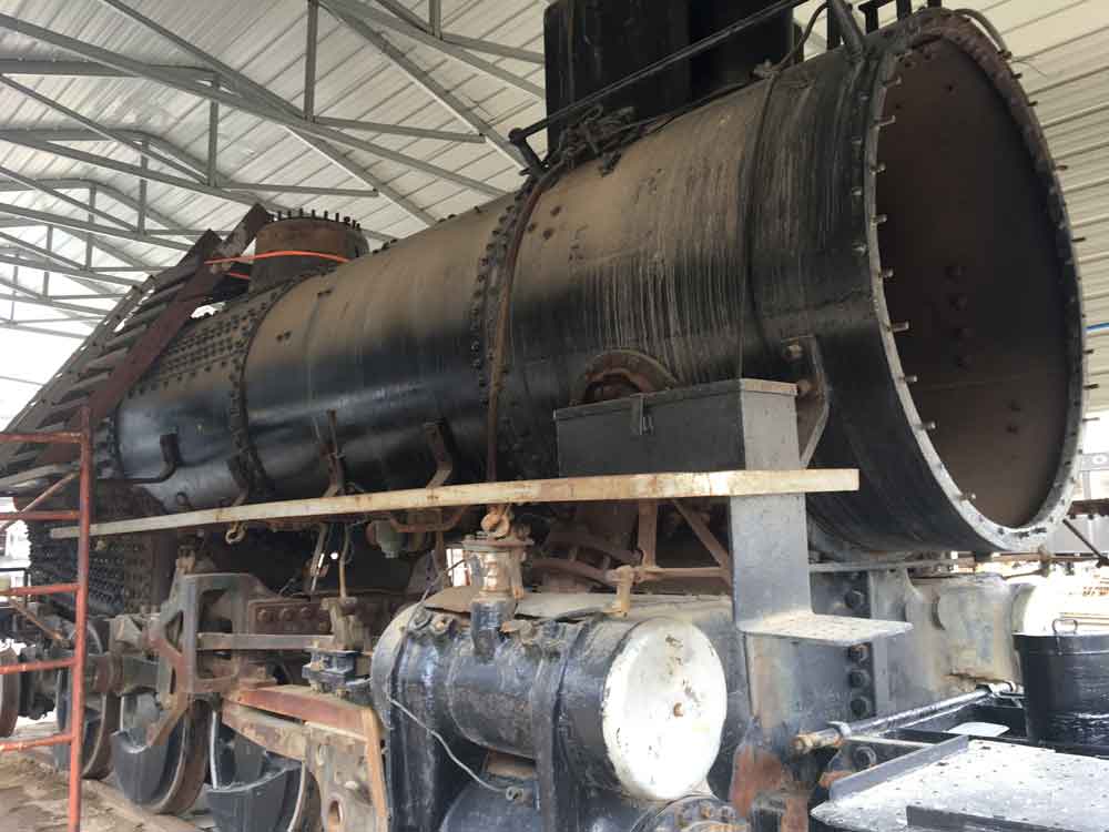
The photos below show the engine as of March, 2021.